BS EN 1838:2013 Emergency Lighting Testing
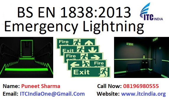
BS EN 1838:2013 Emergency Lighting Testing
| First of all, What is BS EN 1838:2013 standard? This standard states general rules for emergency escape lighting and standby lighting systems installed in an office, property, site, building or working place where such systems are required. These areas are predominantly where the public or workers have access. | ||
| Use of BS EN 1838 can help save life and unnecessary anxiety and confusion can be alleviated by strategically placed visible signs indicating the way out of a location. | ||
| Types of emergency lighting at a location with the objective : | ||
| S.No | Type of lightning | Objective |
| 1 | Emergency lighting | to ensure the safety lighting is provided on the dot in a specified area when the normal mains power supply to the usual lighting installation fails. |
| 2 | Emergency Escape lightning | to enable a safe exit from a location and/or building in the event of failure of the mains’ normal supply |
| 3 | Emergency Escape route lightning | to enable the safe exit from a location or building for occupants by providing appropriate visual conditions and direction finding on escape routes, and in special locations, and to ensure that firefighting and safety equipment can be readily located and used. |
| 4 | Anti Panic Lightning | to enable safe movement of occupants towards escape routes by providing appropriate visual conditions and direction finding. |
| 5 | High-Risk task area lightning | to the safety of people involved in a potentially dangerous process or situation and to enable proper shutdown procedures to be carried out for the safety of other occupants of the location or the building. |
| This standard is for : | ||
| 1. Lightning Engineers | ||
| 2. Electrical Contractor | ||
| 3. Landlords, employers and any individual with responsibility for premises such as hospitals, care homes, hotels, schools, laboratories, theatres, cinemas, concert halls, sports halls, libraries, shops, museums and sports stadium. | ||
| Revised editions of BS EN 1838 has : | ||
| Illumination of the points of emphasis has been clarified and improved and external illuminations have been clarified as needed to extend to a place of safety | ||
| Illumination of fire alarm call points and first aid posts are now consistent, regardless of location | ||
| The colour and style of safety signs is amended to the revised ISO format | ||
| A deviation of some countries has been amended. | ||
| Every employer is required to carry out a risk assessment to identify the risks to people who enter the employer’s premises; | ||
| Measures to be taken on basis of Risk Assessment | ||
| · Provision of safe means of escape | ||
| · Emergency lightning | ||
| · take into account the needs of people with disabilities | ||
| Emergency Lightning Design Checklist : | ||
| 1. Inspection of the risk assessment | ||
| 2. The time span of the emergency lighting | ||
| 3. Discover emergency escape routes and take account of possible dangers. | ||
| 4. Find the locations of fire alarm call points, firefighting equipment and fire safety signs | ||
| 5. Determine the type of emergency lighting system | ||
| 6. Means of isolation for testing and/or maintenance | ||
| 7. Coordination/interface with luminaire manufacturers where main luminaires are to be converted into emergency lighting luminaires | ||
| 8. Discover the exit sign requirements | ||
| 9. Find any high-risk areas | ||
| 10. Open areas larger than 60m² floor areas need to be identified | ||
| 11. Need for external illumination outside final exit doors and on a route to a place of safety. | ||
| Locations : | ||
| It is paramount that the emergency luminaires are placed to give suitable illuminance in the event of a failure of the normal lighting. | ||
| S.no | Area | Details |
| 1 | Open Area | Open areas are often called anti-panic lighting. These are areas larger than 60m² floor area or maybe areas identified by the fire risk assessment as requiring safety illumination |
| 2 | Emergency Exit and escape route | Emergency exits and escape routes should be provided with signs |
| 3 | External areas in the immediate vicinity of exits | In order to assist dispersal to a place of safety, the external areas in the immediate vicinity of final exits should be illuminated in accordance with the illumination level for escape routes, given in EN 1838 (BS 5266-7) of not less than 1 Lux |
| 4 | Lift cars | Lift present a problem because the experience of being confined in the dark within a small space for an indefinite period of time is not only unpleasant but may cause harm to those who are nervous or suffer from claustrophobia |
| 5 | Moving stairways and walkways | Moving stairways and walkways should be illuminated as if they were part of an escape route in the event of mains failure. |
| 6 | Toilet Facilities | Toilet facilities exceeding 8 metres squared gross area should be provided with emergency lighting as if they were open areas. |
| 7 | Switch rooms and plant rooms | Emergency lighting should be provided in all motor generator rooms, control rooms, plant rooms, switch rooms and adjacent to main switchgear or control equipment associated with the provision of normal and emergency lighting to the premises. |
| 8 | Covered car parks | The pedestrian escape routes from covered and multi-storey car parks should be provided with emergency lighting. |
| Duration of battery backup: | ||
| The battery back-up of the emergency lighting system will depend on the use of the building and the evacuation strategy. 3-hour duration is required in places of entertainment (cinemas, theatres, etc) and for buildings that have a sleeping risk (hotels and guesthouses, etc.). | ||
| Lumination Levels | ||
| The level of illuminance required depends on the function of an area. | ||
| Certain specific locations require a specific illuminance and response time the below table gives the locations and response time. | ||
| Location | Minimum luminance(Lux) | |
| Kitchens | 15 | |
| First aid rooms | 15 | |
| Treatment rooms | 50 | |
| Refuges | 5 | |
| PlaPlant rooms switch rooms & emergency winding facilities for lifting rooms, switch rooms & emergency winding facilities for lifts | 15 | |
| Fire alarm control and indicating equipment | 15 | |
| Reception areas | 15 | |
| Panic bars & pads or security devices | 5 | |
| Swimming pool surrounds and diving area | 5 |
If Your Buyers Demanding for Emergency Lighting Testing – Contact Now!
Kindly send us the following Details, So that we can provide you with a quotation for the same:
- Product Name, Technical Specifications, and Brochure
- Product Images
- Total Number of Samples Required: 2
Wish this blog post will help. If you have any other questions, please feel free to contact us. ITCIndia team looking forward to working with you and get better together!
Mr. Puneet Sharma | Call: 08196980555 | E-mail: [email protected]
Get Instant Quotations, Fill the Enquiry form:
Are you looking for Stationary Lead Acid Battery Testing?
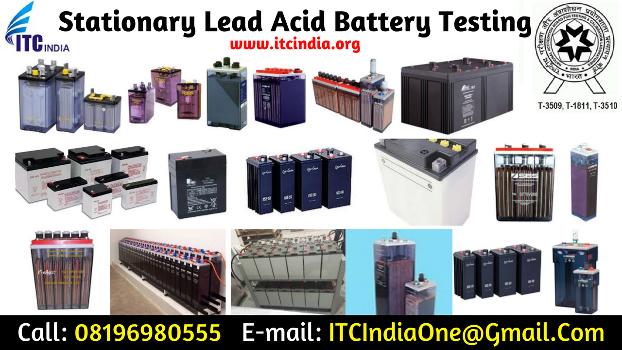
Stationary Lead Acid Battery
IEC 60896-22 is applicable to:-
- All stationary Lead-acid cells
- Monobloc batteries of the valve-regulated type
- For Float charge application: They can be permanently connected to a load and d.c. power supply.
- In a static location: not generally moved from place to place.
They are incorporated into stationary equipment or installed in the battery room.
These kinds of batteries can be used in
- Telecom
- UPS
- Utility switch
- Emergency power or similar applications
The objective of IEC 60896-22:- It specifies the methods of tests for all types and construction of valve regulated stationary Lead acid batteries and monobloc batteries.
Does not applicable :
- lead-acid cells and monobloc batteries used for vehicle engine starting applications
- solar photovoltaic energy systems
- general purpose applications
There is a list of tests performed on the batteries for safe operation characteristics, durability Characteristics & Performance Characteristics.
Safe operation characteristics
|
||
| Test Clause | Measure | Purpose |
| 6.1 | Gas emission | To determine the emitted gas volume |
| 6.2 | High Current Tolerance | To verify the adequacy of current conduction
cross- sections |
| 6.3 | Short circuit current & d.c internal resistance | To provide data for the sizing of fuses in the
exterior circuit |
| 6.4 | Protection against internal ignition from external spark sources | To evaluate the adequacy of protective features |
| 6.5 | Protection against the ground short propensity | To evaluate the adequacy of design features |
| 6.6 | Content and durability of required markings | To evaluate the quality of the markings and the
the content of the information |
| 6.7 | Material identification | To ensure the presence of material identification
markings |
| 6.8 | Valve operation | To ensure the correct opening of safety valves |
| 6.9 | Flammability rating of materials | To verify the fire hazard class of battery materials |
| 6.10 | Intercell connector performance | To verify the maximum surface temperatures of
the connectors during high rate discharges |
Performance characteristics |
||
| Test Clause | Measure | purpose |
| 6.11 | Discharge capacity | To verify the available capacities at selected
discharge rates or discharge durations. |
| 6.12 | Charge retention during storage | To provide storage duration data |
| 6.13 | Float service with daily discharges | To determine cyclic performance under float charge conditions |
| 6.14 | Recharge behavior | To determine the recovery of capacity or
autonomy time after a power outage |
Durability Characteristics |
||
| Test Clause | Measure | purpose |
| 6.15 | Service life at an operating temperature of
40 °C |
To determine the operational life at elevated temperatures |
| 6.16 | Impact of a stress temperature of 55 °C or
60 °C |
To determine the influence of high stress
temperatures on cell or monobloc battery life |
| 6.17 | Abusive over-discharge | To determine the expected behavior when excess capacity is discharged |
| 6.18 | Thermal runaway sensitivity | To determine the expected times to establish a condition of escalating current and temperature |
| 6.19 | Low-temperature sensitivity | To determine the sensitivity toward damage induced by electrolyte freezing |
| 6.20 | Dimensional stability at elevated internal
pressure and temperature |
To determine the propensity of the cell or
monobloc battery to be deformed by internal pressure and at elevated temperature |
| 6.21 | Stability against mechanical abuse of units
during installation |
To determine the propensity of the cell or
monobloc battery to fracture or leak when dropped. |
If Your Buyers Demanding for Stationary Lead Acid Battery Testing – Contact Now!
Kindly send us the following Details, So that we can provide you a quotation for the same:
- Product Name, Technical Specifications, and Brochure
- Product Images
- Total Number of Samples Required: 2
Wish this blog post will be help. If you have any other questions, please feel free to contact us. ITCIndia team looking forward work with you and get better together!
Mr. Puneet Sharma | Call: 08196980555 | E-mail: [email protected]
Get Instant Quotations, Fill the Enquiry form:
Are You Looking for Cable tray Safe Working Load Test (SWL)?
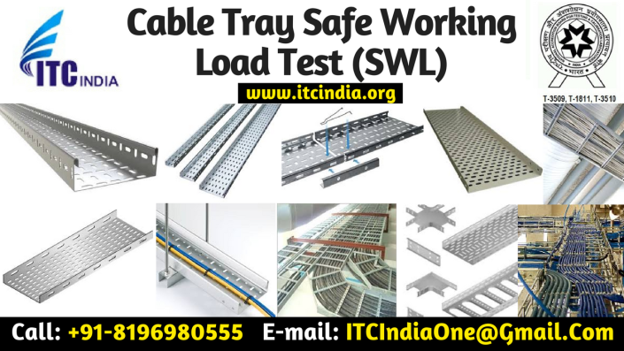
Cable tray Safe Working Load Test (SWL)
Cable tray/ Protective castings must be designed to the below said ambient temperatures
- -25 ºC to 90 ºC for outdoor use
- +5 ºC to 90 ºC for indoor use.
Safe working load is one of the mechanical requirements assigned to meet by the cable tray/ protective castings. Another mechanical requirement is the Impact resistance Test. But in this article we are focusing on Safe Working Load. Testing must be performed at the above declared temperatures.
The criteria that a cable tray must satisfy are:
- The maximum deflection should not exceed L/100 where L is the distance between the supports.
- No mechanical defects or failure are observed when tested at 1.7 * SWL.
How to place the Loads :
All the loads must be uniformly distributed (UDL) over the length and width of the sample. The loads have to be applied in a way that uniform distribution is ensured even in case of extreme deformation of the sample. For settlement of the samples, a pre load of 10 % of the test load unless otherwise specified, should be calibrated to zero.
The gradually increase the load longitudinally and transversely up to the test load continuously or in increments. These increments should not exceed about a quarter of the SWL.
After loading, the deflection should be taken at the points specified to give a practical mid-span deflection.
The samples should be left and the deflection measured every 5 min until the difference between two consecutive set of readings is less than 2 % with regard to the first set of 2 consecutive readings. The first set of readings calculated at this point is the set of deflection measured at the test load.
After this treatment, the test load samples, their joints and internal fixing devices, should show no damage or cracks visible to normal view or corrected vision without magnification.
After this, load is increased to 1.7 times the test load.
The samples should be left and the deflections measured every 5 min until the difference between two consecutive sets of readings is less than 2 % with regard to the first set of the two consecutive sets of readings. The samples should sustain the increased loading without collapsing. Buckling and deformation of the samples is permissible at this loading.
Note:
Tests should be carried out for the smallest and largest sizes of cable
Trays lengths or cable ladder lengths, having the same material, joint and
Topological shape.
If Your Buyers Demanding for Cable tray Safe Working Load Testing – Contact Now!
Kindly send us the following Details, So that we can provide you quotation for the same:
- Product Name, Technical Specifications and Brochure
- Product Images
- Total Number of samples Required: 2
Wish this blog post will be help. If you have any other questions, please feel free to contact us. ITCIndia team looking forward work with you and get better together!
Mr. Puneet Sharma | Call: 08196980555 | E-mail: [email protected]
Get Instant Quotations, Fill the Enquiry form:
Fence Energizer Testing Laboratory
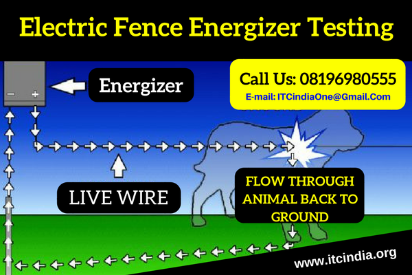
Are you looking for Fence Energizer Testing Laboratory?
If you are looking for Solar Fence Energizer Testing laboratory, then you are at the right place. (ITC India Pvt Ltd). ITC India one of the best Solar Fence Energizer Testing Laboratory in India. ITCIndia NABL Approved in electrical ,electronics, and Photometric Division. If you are Interested for Energizer Testing, then ITC India Can Help You!
For More Information You Can Check our certificate no. T-3509, T-3570 and T-1811.
Fence Energizer Testing Standards:
- IEC 60335-2-76
- IS 302-2-76
Energizer Testing Test as per IS 302-2-76, IEC 60335-2-76
- Protection against Electric Shock,
- Electrical Insulation at operating
Temperature
3. Moisture Resistance
4. Insulation resistance
5. Stability and mechanical hazards
6. Mechanical strength
7. Constructions Internal Wiring,
8. Components,
9. Cord grip and cord guard,
10. Terminals for external conductors,
11. Provision for earthing,
12. Screws and connections,
13. Creepage distances and clearances,
14. Resistance to heat fire and tracking
People Searches related to Fence Energizer Testing:
Solar Zatka Machine Testing, Testing For Solar Fence Guard, Solar Fence Guard Testing , Security Energizers Testing , Security electric fencing Testing , Electric Fence Energizer SMS Controller Testing, Searches related to Security Energizers Testing , electric fence energizer Testing price in India, solar fencing energizer Testing price, solar fencing Testing cost, electric fence energizer Testing India, electric fencing Testing India, electric fence Testing India price, Testing For Solar Fence Guard, Electric Fence Energizer Testing Laboratory, Contact us for Electric Fence Energizer Testing, Get FREE Quote For Fence Energizer Testing, Solar Electric Fence Energizer Testing Delhi, Mumbai, Gurgaon, Noida, Chennai, Hyderabad, Bengaluru, Kolkata, Pune, Ahmedabad, Greater Noida, Uttar Pradesh, Lucknow, Manesar, Haryana, Chandigarh, Kandla, Pune, Maharashtra, Chikkalthana, Nashik, Hospet, Karnataka, Sriperumbudur, Tamil Nadu, Meenambakkam, Tirupur, Coimbatore, Tuticorin, Korba, Raipur, Bhilai Steel Plant, Bhiwandi, Vijayawada, Firozabad, Panna, Panipat, Channapatna, Varanasi, Moradabad, Bareilly, Jamshedpur, Bhagalpur, Tiruppur, Rajahmundry, Bokaro Steel City, Kolkata, Durgapur, Indore, Pithampur, Dibrugarh, Noida, Kannur, Salem, Sivakasi, Kanpur, Rajkot, Kochi, Peenya, Surat, Chhattisgarh, Madhya Pradesh, Andhra Pradesh, Jharkhand, Bihar, West Bengal, Assam, Kerala, Gujarat
Why to choose ITC?
We, ITC India providing service to the client from the last 8 years with 100 % satisfied clients. Being NABL accredited, it is equipped with highly accurate machines, experienced and competent engineers. Customer satisfaction is the quality policy of the company. So, we are here to serve the clients in their testing requirements.
- Reasonable Price: Very competitive price, being one of the best on the market. Moreover, this price has no hidden fees.
- The quality of our support is unmatched: We take support one step further by tailoring our replies to suit your knowledge, expectations and personality.
- We’re passionate about what we do: What sets us apart from the competition is that we’re passionate about the services we provide and quality of support.
- Proven track record: We’ve gained a reputation as a reliable and honest company in the last 7 years with most of our customers coming from reference.
If Your Buyers Demanding for Fence Energizer Testing – Contact Now!
Kindly send us the following Details, So that we can provide you quotation for the same:
- Product Name, Technical Specifications and Brochure
- Product Images
- Total Number of samples Required: 2
ITC India has around 5000 clients from Fence Energizer division from All over India.
Wish this blog post will be help. If you have any other questions, please feel free to contact us. ITCIndia team looking forward work with you and get better together!
Submit Your Request For FREE Sample Test Report!
Mr. Puneet Sharma | Call: 08196980555 | E-mail: [email protected]
Get Instant Quotations, Fill the Enquiry form:
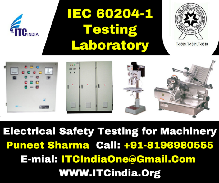
IEC 60204-1 Testing – Electrical Safety Test of Machinery
Electrical Safety Testing for Machinery As Per IEC 60204-1
Are you looking for a lab for IEC 60204-1 testing, and then your search ends at Institute of testing and certification Pvt Ltd (ITC India Pvt Ltd). ITC is a NABL accredited lab in electronics, electrical and photometry. Meticulous machines and proficient engineer are appointed here for the best results. Customer satisfaction is the policy of our company. Let us discuss about the IEC 60204-1 standard relating to machinery. Below are some images of some products under this category……….
What is IEC 60204-1 standard?
This standard is applicable to electrical, electronic and programmable electronic equipment and machine not portable by hand while working including a group of machine working together in a co-ordinate manner.
It implies to Electrical equipment which operate at supply
Voltage <1000V for AC
Voltage <1500 V DC with nominal supply frequency <200 Hz
Power circuit where electrical energy is directly used as working tool are excluded from IEC 60204.
ITC is doing testing of this standard…..
Below is the list of test performed as per this:
| S.no | Name of the clause |
| 1 | Incoming supply conductor terminations and devices for disconnecting and switching off
|
| 2 | Terminal for connection to the external protective earthing system
|
| 3 | Supply disconnecting (isolating) device
|
| 4 | Devices for switching off for prevention of unexpected start-up
|
| 5 | Devices for disconnecting electrical equipment
|
| 6 | Protection against unauthorized, inadvertent and/or mistaken connection
|
| 7 | Protection by enclosures
|
| 8 | Protection by insulation of live parts
|
| 9 | Protection against residual voltages
|
| 10 | Protection by barriers
|
| 11 | Protection against indirect contact
|
| 12 | Protection by application of PELV circuit which have to fulfill following requirements:
|
| 13 | Over current protection
|
| 14 | Protection of motors against overheating
|
| 15 | EQUIPOTENTIAL BONDING
|
| 16 | CONTROL CIRCUITS AND CONTROL FUNCTONS
|
| 17 | OPERATOR INTERFACE AND MACHINE-MOUNTED CONTROL DEVICES
|
| 18 | Control gear: location mounting and enclosures
|
| 19 | conductors and cables
|
| 20 | wiring diagram
|
| 21 | Electric motors and associated equipment
|
| 22 | Accessories and lighting
|
| 23 | Marking, Warning signs and reference designations
|
| 24 | Technical documentation
|
| 25 | Verification of conditions for protection by automatic disconnection of supply
|
| 26 | Insulation Resistance test
|
| 27 | Voltage Test
|
People Searches related to Machinery safety testing laboratory:
Why to choose ITC?
We, ITC India providing service to the client from the last 8 years with 100 % satisfied clients. Being NABL accredited, it is equipped with highly accurate machines, experienced and competent engineers. Customer satisfaction is the quality policy of the company. So, we are here to serve the clients in their testing requirements.
- Reasonable Price: Very competitive price, being one of the best on the market. Moreover, this price has no hidden fees.
- The quality of our support is unmatched: We take support one step further by tailoring our replies to suit your knowledge, expectations and personality.
- We’re passionate about what we do: What sets us apart from the competition is that we’re passionate about the services we provide and quality of support.
- Proven track record: We’ve gained a reputation as a reliable and honest company in the last 7 years with most of our customers coming from reference.
If Your Buyers Demanding for IEC 60204-1 Testing – Contact Now!
Kindly send us the following Details, So that we can provide you quotation for the same:
- Product Name, Technical Specifications and Brochure
- Product Images
- Total Number of samples Required: 2
